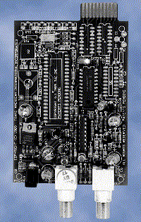
STDCT-PCB
Each slave will have a control for a different gray scale of
the characters and opaque border jumper selectable per camera.
The position of the T/D will be identical to the master.
The standard display is 14 video lines on the STDCT-PCB.
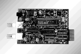
uSTDCT-PCB
The character height of the uSTDCT-PCB allows the user
to select four different character sizes via jumpers on the PCB.
The height is selectable between 7 or 14 video lines, and
the width is standard full width or half width, independent for
each camera. Each slave will have a control for a different gray
scale of the characters and opaque border jumper selectable
per camera. The position of the T/D will be the same as the master.
uSVHTDCT-PCB
The uSVHTDCT-PCB allows the user to independently
adjust gray scale, four character sizes and opaque border. It
also includes two additional controls to position the T/D
independently on each camera.
| Master/Slave Specifications |
- Video Input (BNC)...... 1VP-P Terminated
- Video Output (BNC)...... 1V P-P Terminated
......2V P-P Unterminated
- Power ( DC Coax)...... 9 - 12 VDC
- 2.1 mm x 5.5 mm...... 130mA
- Battery Backup (NiCad)...... 90 Days
......with 24 hr. charge
- Mechanical...... PCB (3.3"W x 4.3"Lx 6"H)
- Clock Accuracy...... Better than +/- 20 ppm
- Date...... Month, Day, Year, Day of Week
- Time...... Hours, Minutes, Seconds, AM/PM
- Title...... 2 lines of 20 characters max.
.......A-Z, 0-9,?,!,',., (blank)
- Display...... White to Black (8 levels)
......Gray Matte (jumper selectable)
......T/D Only or Title or both
- Transformer...... 9 VDC @ 250 mA min.
......UL Rated with 6' cord &plug
- Video S/N...... better than 52 dB
- Video BW...... better than 7 Mhz
- Warranty...... One year Parts and Labor
|
|
| How to order a Master Time/Date/Titling
system from AVE. | |
For this example, let's order a Master Time/Date system.
First, determine the number of Video channels we
will need. In this case we'll say it's 16.
We'll need 1 Master Time/Date board for our system
and this counts as one channel.
This would be (1) MTDCT-PCB
This leaves 15 slave channels.
Determine the features needed from the AVE slave
boards available.
STDCT-PCB
Standard slave board with normal size characters.
uSTDCT-PCB
Slave board with four character sizes.
uSVHTDCT-PCB
Slave board with four character sizes, and
independent horizontal and vertical display positioning.
Remember, the Time/Date display from the master will appear in
the same place on each slave module unless you order the
uSVHTDCT-PCB slave boards. The
uSVHTDCT-PCB allows for independent positioning of each channels display; however, it references the slave's
text position from the master's text position.
We decide that we need the ability to move each
camera's display independently of the Master TDCT. For our
other 15 channels we will use the uSVHTDCT-PCB.
Our order now is:
1-MTDCT-PCB
15-uSVHTDCT-PCB
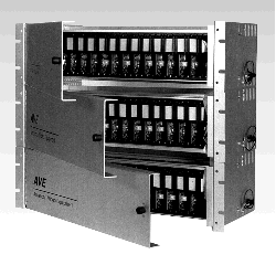
Now we need to order the RACK Mount to house the
16 PCB's. There are two choices:
RACK-OF & RACK-BP. Both racks hold 16 cards
each. The RACK-OF is a 16 card rack with a hinged door
and an open frame. If you order this one you will need
to order seperate power supplies for each board.
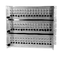
The RACK-BP is a 16 card rack with a hinged door and
a backplane with all power connectors for each PCB
bussed to a terminal block. You will need a Power supply
that provides a minimum of 3 amps (not supplied).
Let's order the RACK-BP. Our order now is:
1-MTDCT-PCB
15-uSVHTDCT-PCB
1-RACK-BP
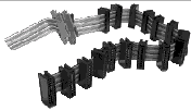
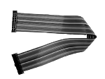
The last component we need is the ribbon buss
which connects all 16 cards together. This is the RB-16. So
our equipment list for a 16 channel Master/Slave
Time/Date system is
1-MTDCT-PCB 15-uSVHTDCT-PCB
1-RACK-BP 1-RB-16
|
|
